When we create a DXF file it is because we are wanting to translate a 3D model into a 2D model. Usually, this is done for manufacturing i.e. a flat pattern of a sheet metal part. Because of this, it is important that our information is translated correctly in the correct orientation so that manufacturers have accurate manufacturing instructions.
So how do we control the output orientation of a DXF flat pattern?
The generated orientation of a sheet metal flat pattern will be the same as the orientation used when modeling your initial base flange. The face that is selected in the front view when the base flange is created will normally be the top surface. Because of this, when creating your base flange you should make sure to create a sketch in the orientation that you require with respect to the X and Y-axis.
However, there are also a couple of options that can be used to change the flat pattern orientation.
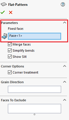
The first option is used to change the flat pattern orientation of a pre-existing part, to do this the following steps can be followed:Navigate to the Flat-Pattern feature in the FeatureManager and right click and Edit the feature
Under Parameters select the new Fixed face (this will be the new top surface

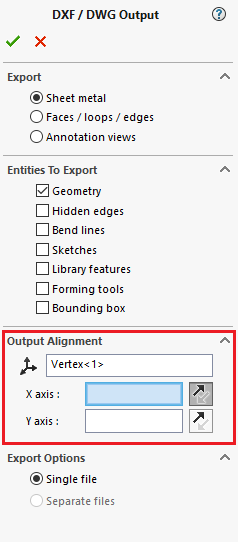
The second option is the use of the Output Alignment setting in the DXF / DWG Output options. This can be achieved using the following steps:Navigate to the Output Alignment setting when creating your DXF/DWG and select any vertex (this can be left blank if you are using the existing model origin as the DXF/DWG file origin)
Then select an orthogonal edge for the X or Y reference axis. The DXF / DWG Output can be aligned to any orthogonal model edge.
The origin can now be placed on any vertex. If you need to modify the reference direction you can click on the ‘reverse’ button.
