Even for advanced FEA users the definition and analysis of contact interactions is not quite straightforward and is vulnerable to modeling errors as contact interactions can introduce non-linearities in the FEA model. The assumptions and theory behind contact interactions need to be understood in order to avoid these modeling errors and generate accurate, robust, and reliable results.
When using contact interactions in SolidWorks simulation, one should know the difference between linear and non-linear contact interaction and the implication of various contact interaction settings.
Linear Vs. Non-Linear Contact Interactions:
Basic no penetration contacts in a static study default to a “Linear” contact algorithm where certain assumptions are made to improve solution speed. These assumptions are:
- Very small or no gaps between contacting parts.
- Little or no sliding between contacting surfaces.
- Faces that touch stay in contact.
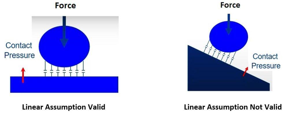
- External load is parallel to contact element as shown below

If any of the above “linear” conditions are violated, the user then needs to choose Large Displacement option in static study properties, or define a non-linear study to determine accurate contact interactions between components. Be advised that a static study using Large Displacement will take longer to solve.
Also, it is important to know, that if Large Displacement is not turned on while violating the conditions of the linear contact algorithm, the linear solution may complete without any warning messages but that doesn’t mean the solution is correct.
Contact Interactions Settings:
There are three main contact interactions settings:
- Node -to- Node
- Node -to- Surface
- Surface -to- Surface
The table below summarizes when each type of the settings should be used and how it affects the accuracy speed and robustness of the FEA model.

Note: If a Large Displacement option is required in a static study, then, Node to-Node contact interaction should be avoided.
In general the surface – to – surface contact takes more time but is the best to use as it works for almost every scenario except where the contact area is extremely tiny such as contacting lines or points.
Other Contact Tips:
Some general contact tips that might help you modify the geometry and select the correct settings are given below.
- Using split lines to reduce source area can improve solution efficiency.
- Using split lines to reduce the target area will have no effect on the solution.
- In general, a more refined mesh on contact faces will result in better and faster converging contact.
- Too fine a mesh on a Target surface could cause convergence issues.