New version 2.5 just released!
Your file admin done in minutes, not hours
Your #Task personal assistant is SOLIDWORKS automation software that automates tasks, batch processes your files, and saves you hours on file admin.
#Task Testimonial
“On a 100-part design, generating the full production package used to take around five hours. Now it’s automated – what used to be three minutes per part is done in a single batch process in #Task in a matter of minutes.
#Task handled all output generation, which saved around five hours. The ability to integrate custom macros meant the project was delivered faster, more consistently, and with lower risk of errors.”
- Daniel Booth, Founder of PROCADFAB
Why #Task?
Built for engineers who want to do more in less time, without risking design quality while saving hours on file admin.
Without #Task:
- Manual file edits
- Risky macros from online forums
- Missing file references
- Unanchored components in assemblies
- Time-consuming PDF exports
- License chaos
With #Task:
- Automated macros save hours
- Trusted, supported plugins
- Find & report with a click
- Auto-fix floating parts
- Batch PDF with naming & zoom controls
- Web portal with admin control
Still using an older version?
The industry’s most powerful batch automation tool just got even better.
Looking for a great deal? Contact us today and our friendly specialists will get back to you.
Here’s what you’re missing:
- Improved performance
- Admin-friendly licence controls
- Powerful new macros
- Compatible with all versions of SOLIDWORKS
Save hours. Reduce errors. Stay in flow.
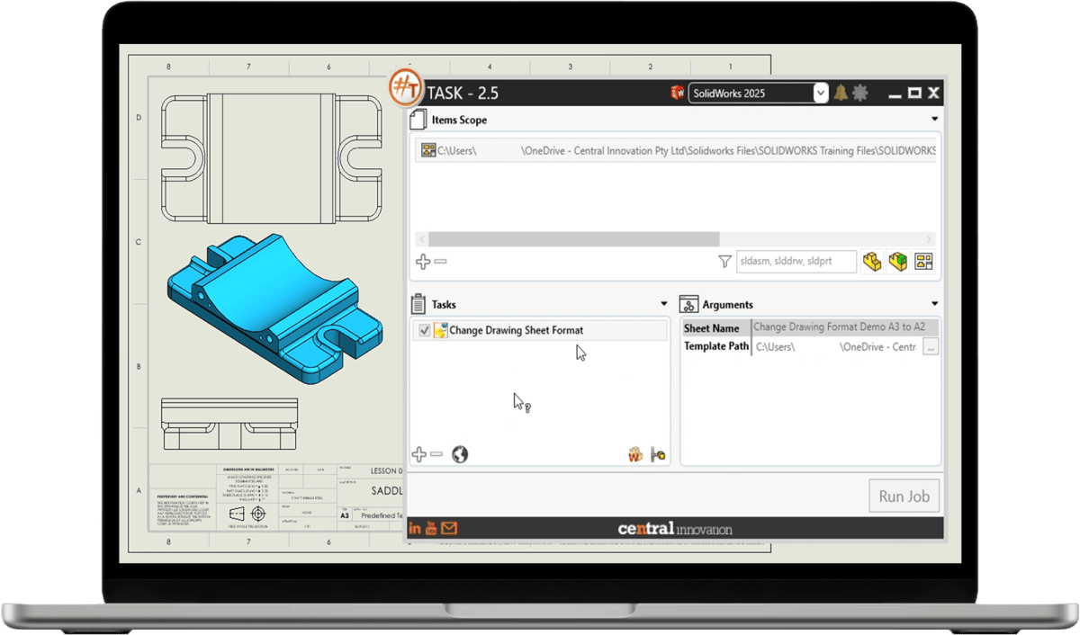
What’s new in #Task v2.5?
Compatible with all versions of SOLIDWORKS
Get full support for the latest parts, drawings and assemblies — futureproof your workflows.


Secure environment & intuitive interface
Manage users and permissions via a secure web-based licence portal — no more spreadsheets or manual key handling. Ideal for multi-seat, multi-site deployments.
7 new built-in macros for SOLIDWORKS
Eliminate repetitive tasks and manual edits with automation macros built for real-world engineering workflows:
- Change document units
- Change drawing sheet format
- Insert blocks in drawings
- Fix floating components in assemblies
- Find missing references (with Excel export)
- Save PDF with Zoom Fit
- Save PDF named by sheet title
Built for engineering scale
Whether you're a solo designer or managing a small team of users, #Task is purpose-built to support batch processing and bulk update SOLIDWORKS files at any scale.
#Task EULA
For more information on using #Task, please read our End User Licensing Agreement here - #Task EULA