Dimension Type setting (Drawings)
Tips and Tricks • Micah • 26 June 2015
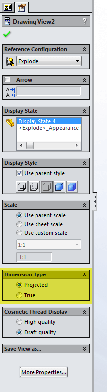
Dimension Type
Often on support customers come to us with drawings that have incorrect dimension values on drawing views.
More often than not the issue is related to a setting in drawing view property manager. The setting is located toward the bottom of the view property manager called “Dimension Type”.
SolidWorks® Help Files definition:
Dimensions in drawings are either:
- True Accurate model values.
- Projected 2D dimensions.
The dimension type is set when you insert a drawing view. You can view and change the dimension type in drawing view Property Managers.
The rules for dimension type are SOLIDWORKS specifies Projected type dimensions for standard and custom orthogonal views and True type dimensions for isometric, dimetric, and trimetric views.
If you create a projected or auxiliary view from another view, the new view uses Projected type dimensions, even if the original view used True type dimensions.
So if you’re adding dimensions to a view and are finding them to be incorrect?
This can occur if the drawing views are using “True” dimensions instead of “Projected” dimensions. In general, conventional drawing views should use projected dimensions; true dimensions should be used for 3D views such as isometric and diametric.
Note: if you change this dimension type setting you will lose all dimensions that you’ve already placed in the view.