Thomsen Motorsport: Project FVT05 Part 1 & 2
News • Central Innovation • 15 November 2016
Car enthusiast, Simon Thomsen of Thomsen Motorsport, is undertaking the design and construction of a Formula Vee vehicle (FVT05) using SOLIDWORKS which he plans to race competitively in 2017. Intercad, the largest distributor of SOLIDWORKS in Australia and New Zealand, is Thomsen Motorsport’s official technology partner.
Formula Vee is an internationally recognised competitive class. Formula Vee Vehicles use a VW engine, gearbox and suspension; which represents the ultimate in simple, but effective technology in an affordable race car package.
Formula Vee is a fiercely competitive class putting emphasis on the skill of modification and driving rather than budget capacity. Because of this, Formula Vee is a popular a stepping stone into higher levels of motorsport.
Simon’s approach is unique and practical. He is able to design, draft and test modifications to the vehicle using SOLIDWORKS before he makes modifications in the workshop. This is extremely useful because he can refine changes to his vehicle using SOLIDWORKS, without the need for extensive and expensive testing or prototyping.
Over the coming months, Intercad will be showcasing the design and construction of Simon’s FVT05 vehicle in SOLIDWORKS as it becomes a reality.

Part 2 – Ergonomics Jig and Bodywork Plug
Construction begins! Simon makes full use of his workshop and gets to work on what promises to be a lengthy but fulfilling project. First things first, an ergonomics jig is designed on SOLIDWORKS and is constructed in the workshop to ensure Simon fits comfortably in his car.

The aim of creating this jig is to ensure there is adequate leg room in the cockpit, and to check that there is no discomfort or interference when using with the pedals or the steering wheel. Furthermore, this jig gives a feel for the alignment of the steering wheel and placement of the mirrors. Simon was also able to check the perspectives of his mirrors using SOLIDWORKS renderings, a useful functionality that is available through Photoview360 and SOLIDWORKS Visualize.

If changes need to be made, they can easily be drafted in SOLIDWORKS before they are done in the workshop. This ensures accurate dimensions and alignment in the design before the actual modifications are made on the vehicle itself also saving material wastage and time, which are critical throughout the project.
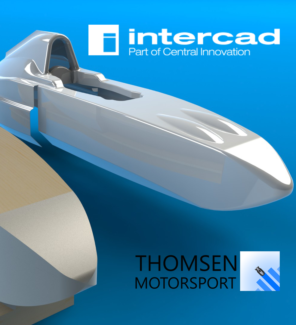
From here, the main shape of the car is built around the ergonomics jig. The bodywork plug is shaped according to the SOLIDWORKS design and renderings. High-density foam is used to form the streamlined shape of the car.

The foam is positioned then cut using a hot-wire cutter (heated steel string) for the front, lower and rear undercuts as well as the nose. The sides then have thin MDF (medium density fibreboard) glued and nailed over the top of the foam to form a strong outer surface. This is the last of the wood needed to construct the car.

The mid-rear bodywork foam sections are carefully fitted, glued and held in place with clamps to ensure the streamlined profile of the design.

From here, Simon will be adding the engine cowling and roll hoop covers which will almost complete the bodywork. The next post will cover the bulk of the metalwork – including the transmission upper sub-frame and chassis.

You can discover more on Simon’s project here.