Reducing Size/Optimizing Large Step Files in Top-Level Assembly
Tips and Tricks • Jalal • 18 November 2021
Manufacturing, MFG - Tips and Tricks, SOLIDWORKS

Sometimes large step files imported in a top-level assembly are for references and mating purposes and the features themselves are not important. There are a couple of ways you can reduce the size of the file or optimize it for mating in top-level assembly.
1. Reducing size (Converting Solid-body to exterior surfaces only):
This method can be used if only exterior surfaces of the solid bodies are needed for assembly referencing and mating and the actual solid body is not of importance. This method can also help reduce the size of the step file drastically.
The procedure to convert the solid body to exterior surfaces only is as follows.
- Import the step file containing the solid body
- Save it as a SolidWorks part file with exterior surfaces only (making it a surface), then
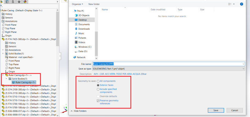
- Open the SolidWorks part file you saved in step 2 and
- Export it again as a step file.
- You can then use 3D interconnect to import the step files and maintain a link to the step file with exterior surfaces only.
The main drawback of this method here is that if your step already contains lots of surfaces then this option in step 2 is not available. Make sure the step file contains solid bodies before importing. If the step file belongs to another CAD system, tell the supplier to send you a step file with solid bodies only, which you can then convert to exterior surfaces.
This method can also be sometimes used with other imported file types like Parasolid etc. and can also be used to simplify a SolidWorks sub-assembly or top-level assembly containing a large number of mates and references.
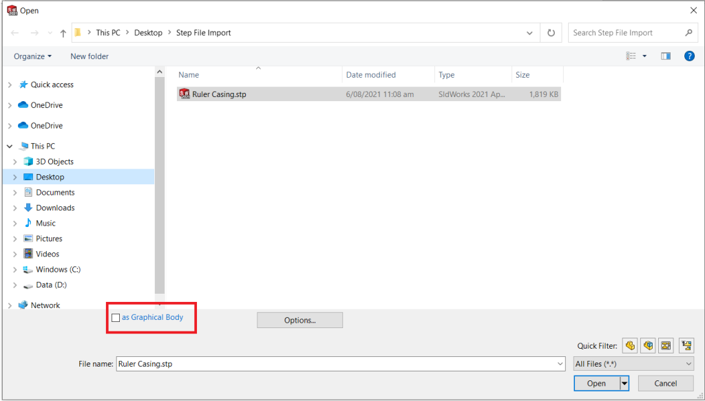
2. Importing Step file as graphics body:
One way is to import the step file as a graphics body. This is the fastest way to deal with imported files with almost no effect on the performance of the assembly but a major drawback of this is that it can only give you a visual representation of that imported part and no interaction with the features is possible including mate referencing.
3. Optimizing Step File in Top-Level Assembly
The method highlighted above might not always be the preferred way to import a file, especially if the users want all the features, bodies, and surfaces in the step file to be imported as it is and the features themselves are important. Therefore, in this case, the user should know how to optimize the top-level assembly performance and make sure that resources are allocated to features of interest only.
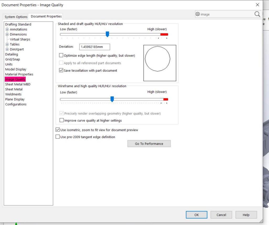
Adjusting Image Quality Settings:
When importing step files with extremely large sizes and features, it is always important to check and adjust image quality settings. Try reducing these settings if the assembly performance is extremely slow. These settings can help in getting the balance between performance and speed.
Tweaking display settings of individual parts or assemblies to shaded or hidden lines only and hiding parts you are not using can also speed things a little bit up.
Using Mated or Graphics SpeedPak of Sub-Assemblies:
The other thing that significantly optimizes the top-assembly performance is using SpeedPak. This is an extremely handy tool especially, when only portions of the imported geometry are required for mating or references, and the remaining geometry is purely for graphical purposes. Users can consider using SpeedPak to create ultralight representations of their geometry.
As only sub-assemblies in SolidWorks can be SpeedPaked therefore, to SpeedPak an imported step file the procedure below can be followed
- Import the step file,
- Save the imported step file as SolidWorks part file.
- Insert the new part file created in step 2 into its own assembly,
- Then save the new assembly file.
- Open the newly created sub-assembly in the top-level assembly to access SpeedPak options.
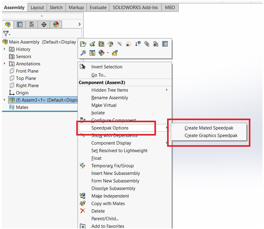
Now there are two ways to SpeedPak a sub-assembly as shown below
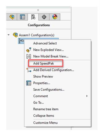
Within the top-level assembly file, go to the Configuration Manager tab, right-click the configuration, and then click Add SpeedPak. The user is then prompted with the features in the sub-assemblies to be SpeedPaked.
Another way is to do all the mating first and then in the feature manager tree right-click and select SpeedPak options and then click mated SpeedPak.
S. Jalal Farid
Applications Engineer Central Innovation
At Central Innovation, we can provide all – or part – of the solution. Including SOLIDWORKS, ARCHICAD, and many more industry-leading tools.
It’s something we’ve been doing for almost 30 years. Our commitment to customer service is second to none: we help you get the best out of your technology.
For a truly unique solution to your unique challenges, please contact us. Or read about some of the great services and solutions we offer.
New South Wales – Head office | CAD software supplier
The best solution is one tailored to your needs. Let’s discuss your options, at our New South Wales Central Innovations head office. Or call us or email us.